


IPSec & VPN Tunnel
Tutorial Overview
This lab is an introduction to IPSec and VPN Tunnels, where you will create a VPN and use IPSec to configure the permissions of the tunnel. This lab is broken down into four sections. The first section will describe the lab and the overall objective. The second section covers all the technical details you much know to complete the lab objectives. The third sections covers the VPN parameters and capturing traffic with Ethereal. The final section holds the lab report format. This lab is used in IS2820/TELECOM2813 Security Management.
Preliminary Questions
Lab Resources
Lab Objective
The network structure for this lab is shown in figure 1. All computers shown have the IP addresses displayed in the figure and are configured as FTP1 and Telnet servers.
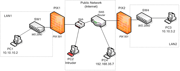
Figure 1.
You must establish an IPSec VPN tunnel between the two firewalls (PIX 501) so that the traffic that flows through the tunnel from LAN1 to LAN2 is encrypted and cannot be interpreted by any intruder in the public network.
Requirements & Criteria
Part A Requirements
- Allow telnet access to PC1 from any PC outside LAN1.
- PC1s true IP address should not be revealed so it is recommended that you create a static NAT entry for PC1
- Configure NAT in PIX 1 and PIX2
- Establish a telnet session from PC3 to PC1 and capture the session’s traffic with Ethereal on PC2 (The Intruder’s PC). Login from PC3 to PC1 with your seclab account.
- Analyze the captured traffic and determine the packets in which the seclab’s account password is being sent.
- The FTP service is not started automatically when you log in. You’ll have to activate it by following the procedures mentioned later in this document
Compliance Criteria for Part A
- Users from the networks outside LAN1 (PC3 and PC4) can telnet to PC1
- Traffic from the private network that goes into the public network must not reveal the private network’s IP addresses.
- The traffic flow between LAN 1 and LAN 2 can be captured for your analysis.
Part B Requirements
- Reconfigure PIX1 and PIX2 to establish an IPSec VPN tunnel between them that will secure traffic flowing from LAN1 to LAN2. This means, securing traffic that will flow from 10.10.10.0 to 10.10.3.0. For true VPN functionality, NO address translation must affect traffic flow between LAN1 and LAN2 ONLY. Additionally, services on LAN1 and LAN2 should work for any user of either LAN.
- Establish a telnet session from PC3 to PC1 and capture the session’s traffic with Ethereal on PC2. Login from PC3 to PC1 with your seclab account.
- Analyze the captured traffic and determine the differences with the packets captured for a similar session in part A.
- Can you access any service on the PCs of LAN1 or LAN2 from PC4 ? Can the PCs from either LAN access services on PC4 ? What does this tell you about the security of the VPN tunnel you have configured?
Compliance Criteria for Part B.
- Telnet and FTP access among the computers on LAN1 and LAN 2 works. (PC1 can Telnet to PC3 and vice versa, PC1 can FTP to PC3 and vice versa)
- The captured traffic flow between LAN1 and LAN2 shows encrypted packets.
Technical Details
Address Pools
LAN1’s internal (private) address pool for its network is 10.10.10.0 with a netmask of 255.255.255.0
LAN1’s external (public) address pool is 192.168.2.1 – 192.168.2.63. However, 192.168.2.1 has to be assigned to PIX1’s outside interface.
LAN2’s internal (private) address pool for its network is 10.10.3.0 with a netmask of 255.255.255.0
LAN2’s external (public) address pool is 192.168.10.1 – 192.168.10.63. However, 192.168.10.1 has to be assigned to PIX2’s outside interface.
IP Addresses for the PIX Firewalls
PIX1 will have an inside interface of 10.10.10.1 and an outside interface of 192.168.2.1. PIX2 will use an inside interface of 10.10.3.1 and an outside interface of 192.168.10.1.
Routing Information and Default Route Settings
Traffic between LAN1 and LAN2 has to go through a public routed network in this assignment. The routing settings for this network have been set for you but you must take care of indicating the correct default gateways to the firewalls that will take care of the traffic of LAN1 and LAN2. On PIX1 you need to set the default gateway to be 192.168.2.65 and PIX2 you need to set the default gateway to be 192.168.10.65.
Configuring the PIX firewalls
In order to configure the PIX firewalls you will connect the blue cable that ends in a serial adapter to the serial port on the back of PC1. Once you log in to your user account (explained later) you can activate the Connect to Serial Port icon located on your desktop. Press the Enter key several times to “wake up” the connection.
When you are finished configuring one of the PIX, simply pull out the blue cable and connect it to the Console port of any other PIX you need to configure.
You will not be using the PIX Device Manager’s graphical user interface to configure the firewall in this assignment.
Erasing previous configurations on the PIX firewall:
Before starting to configure the PIX firewall you should erase any previous configuration already stored on it so that you can start your work from an unconfigured system. To do this enter privileged mode on the PIX firewall and use the following commands:
- write erase
- reload
These commands erase the current configuration from the flash memory of the PIX and reboot the firewall. To start configuring the PIX answer yes to any prompt that shows up except for the one that says Pre-configure PIX Firewall now through iterative prompts? to which you should answer no.
After all this you’ll be left at the prompt of the unprivileged mode of the PIX. Since there is no configuration stored on it, the enable (privileged mode) password is blank. When asked for the enable password just press the Enter key.
When you have finished this lab assignment, erase the configuration that you have provided to the PIX firewall so the next student team will also start from an unconfigured system.
Login for the Windows Machines
For your work in this lab you will use the username seclab with password seclab1 on all Windows 2000 based machines.
Telnet and FTP Service Activation
The PCs for this lab are the Windows 2000 Professional machines that have been labeled PC1, PC2 and PC3. These machines have the Telnet service installed and activated. However, for this lab you have to manually activate the FTP Server service on a machine if it has not previously been activated. You can do this by clicking on the Start FTP Server icon on the Desktop screen of each PC.
When you activate the FTP Server, you should see the initial screen of the Quick’n easy FTP server. If not, check to see if you have a small icon on the lower right hand corner of your screen and click on it to activate the initial screen (the icon looks like a small world globe with a stripe running diagonal across it).
Once on the initial screen of the Quick’n easy FTP server click on the Start button to start the FTP service on that machine.
Establishing an FTP Session
To establish an FTP session from machine A to machine B do the following:
- Open a command screen from machine A: Select Start -> Run and write cmd in the Run command window. A black text based window should open up.
- On the command screen to start an FTP session of machine B by using ftp <ip_address_of_Machine_B>
- Login as user anonymous , there is no password so you can press the Enter key at the password prompt.
- When you want to logout of the FTP server type quit
Establishing a Telnet Session
To establish a Telnet session from machine A to machine B do the following:
- Open a command screen from machine A: Select Start -> Run and write cmd in the Run command window. A black text based window should open up.
- On the command screen to start an FTP session of machine B use telnet <ip_address_of_Machine_B>
- Login as user seclab , the login password is seclab1. If you are prompted for a domain, just press the Enter key
- When you want to exit the telnet session type exit.
VPN Tunnel Parameters
- Use only ESP since traffic is going through a “public” network.
- Use pre-shared keys for device authentication. The key can be a string of characters and numbers selected by you. Example: cisco123.
- For encryption use DES only.
All other parameter values (DH group, HMAC standard, etc) should be chosen by each student group.
Running Ethereal to Capture Packets
The software application Ethereal is installed on all computers of the security lab. However for this lab you will only need to activate it in PC2 . To activate Ethereal and start a packet capture, do the following:
- Login into each machine as seclab
- Activate the Ethereal icon that is on the Desktop
- Go to the Capture menu and click on the OK button to start the packet capture. A capture progress window should pop-up.
- Once enough packets have been captured or enough time has elapsed, click on the Stop button. Capture only the packets you need in order to make your analysis easier.
- Once you have stopped the packet capture, you should be able to recognize three different screen sections: The packet list section (upper section), the packet details section (middle section) and the packet bytes section (lower section). Each time you select a packet in the packet list section the other two sections will change accordingly. You can now analyze the captured packets as you wish.
The Filter text field on the main screen allows you to specify which packets should be displayed on the packet list section of the screen. Use this to get a view of only those packets that you are interested in. For example, if you write telnet in this field you will only see the packets related to a captured telnet session.
Lab Report
The lab report for this assignment should include:
- Answers to the questions posted in the Preliminary Questions section of this assignment.
- Printout or screen capture of one of the packets captured with ethereal for part A and another for part B.
- Include the configuration file that satisfies the requirements of Part A and the configuration file that satisfies the requirements of Part B (or a list of changes that you had to do to Part A’s configuration). Include a list of the VPN parameters that were chosen by you and their respective values.
- Explain the information contained in at least one of the packets that relate to task 1 of part A
- Write down the analysis you completed for task 1 of part B
- Answer the questions mentioned in task 2 of part B
To capture the configuration of the firewall, open a Terminal connection through the console port of the firewall (as explained in the introductory session) , enter privileged mode and execute the show running configuration command (The short version is sh run). Then select the configuration text and press Ctrl-C. Open a text editor (like Wordpad) and paste the configuration text with Crl-V. Save the file and include its contents in the report.