


Firewall Access Control Lists
Lab Overview
This introduce you to a hardware firewall and the basic commands that are required to establish access control lists. The lab is broken down into four sections. The first section will list the resources that are required to complete this lab, ask preliminary questions, and describe the lab in detail. The second section lists the technical details that you will use to complete the lab. The third section covers establishing a Telnet and FTP session. The final section covers the format the lab report should be in. This lab is used in IS2820/TELECOM2813 Security Management.
Lab Resources
Preliminary Questions
If you enable ping during the testing/debugging phase of your configuration process make sure that you take out any configuration changes that allowed ping (ICMP) traffic to go through the firewall before turning in your results.
Lab Objective
The network structure for this lab is shown in figure 1. All computers shown have the IP addresses displayed in the figure and are configured as FTP1 and Telnet servers.
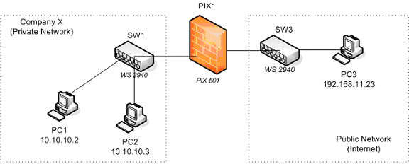
Figure 1
Requirements & Criteria
You must restrict the traffic between the Company X’s private (inside) network and the public (outside) network according to the following requirements:
Part A Requirements
- Permit FTP access from the public network to PC1 in the private network, no private IP addresses should be exposed in the process.
- Telnet access from the public network to PC1 is not to be allowed
- FTP and Telnet from the public network to PC2 is not to be allowed
- FTP and Telnet access from the private network PCs to the public network PCs is allowed.
- The true IP addresses of the computers on the private network should not be seen in the public network.
- Use the address pools that are mentioned in section IV
Compliance Criteria for Part A
- Users from the public network should be able to FTP to PC1 but not to PC2. Users FTP to PC1 without directly using one of Company X’s private IP addresses.
- Traffic from the private network that goes into the public network must not reveal the private network’s IP addresses.
- Telnet access from the public network to PCs in the private network should not work
- Telnet and FTP access from the private network PCs to the public network’s PCs works.
Part B Requirements
- Modify the configuration of Part A to deny FTP and Telnet access from private network PCs to the public network
- FTP service is not started automatically when you log in. You’ll have to activate it by following the procedures mentioned later in this document
Compliance Criteria for Part B
- Satisfy compliance criteria 1, 2 and 3 of part A
- Telnet and FTP access from the private network PCs to the public network’s PCs does not work.
Technical Details
Address Pools
Company’s X private address pool for its network is 10.10.10.0 with a netmask of 255.255.255.0. Their public address pool is 192.168.11.0 – 192.168.11.7 although only addresses from 192.168.11.1 – 192.168.11.6 are usable.
Configuring the PIX1 Firewall
In order to configure the PIX1 firewall you will connect the blue cable that ends in a serial adapter to the serial port on the back of PC1. Once you log in to your user account (explained later) you can activate the Connect to Serial Port icon located on your desktop. Press the Enter key several times to “wake up” the connection. You will not be using the PIX Device Manager’s graphical user interface to configure the firewall in this assignment.
Before starting to configure the PIX firewall you should erase any previous configuration already stored on it so that you can start your work from an unconfigured system. To do this enter privileged mode on the PIX firewall and use the following commands:
- write erase
- reload
These commands erase the current configuration from the flash memory of the PIX and reboot the firewall. To start configuring the PIX answer yes to any prompt that shows up except for the one that says Pre-configure PIX Firewall now through iterative prompts? to which you should answer no.
After all this you’ll be left at the prompt of the unprivileged mode of the PIX. Since there is no configuration stored on it, the enable (privileged mode) password is blank. When asked for the enable password just press the Enter key.
When you have finished this lab assignment, erase the configuration that you have provided to the PIX firewall so the next student team will also start from an unconfigured system.
Login for the Windows Machines
For your work in this lab you will use the username seclab with password seclab1 on all Windows 2000 based machines.
Telnet and FTP
Telnet and FTP Service Activation. The PCs for this lab are the Windows 2000 Professional machines that have been labeled PC1, PC2 and PC3. These machines have the Telnet service installed and activated. However, for this lab you have to manually activate the FTP Server service on each machine if it has not previously been activated. You can do this by clicking on the Start FTP Server icon on the Desktop screen of each PC.
When you activate the FTP Server, you should see the initial screen of the Quick’n easy FTP server. If not, check to see if you have a small icon on the lower right hand corner of your screen and click on it to activate the initial screen (the icon looks like a small world globe with a stripe running diagonal across it).
Once on the initial screen of the Quick’n easy FTP server click on the Start button to start the FTP service on that machine.
Establishing an FTP Session
To establish an FTP session from machine A to machine B do the following:
- Open a command screen from machine A: Select Start -> Run and write cmd in the Run command window. A black text based window should open up.
- On the command screen start an FTP session of machine B by executing: ftp <ip_address_of_Machine_B>
- Login as user anonymous , there is no password so you can press the Enter key at the password prompt.
- When you want to logout of the FTP server type quit
Establishing a Telnet Session
To establish a Telnet session from machine A to machine B do the following:
- Open a command screen from machine A: Select Start -> Run and write cmd in the Run command window. A black text based window should open up.
- On the command screen start an FTP session of machine B by executing: telnet <ip_address_of_Machine_B>
- Login as user seclab , the login password is seclab1. If you are prompted for a domain, just press the Enter key
- When you want to exit the telnet session type exit.
Lab Report
The lab report for this assignment should include:
- Answers to the questions posted in the Preliminary Questions section of this assignment
- Evidence that you satisfy two of the compliance criteria for Part A and Part B by posting the screenshots or text of any kind of test that you conducted to verify such compliance.
- Final configuration of the PIX firewall that satisfies all the compliance criteria. Include the configuration file that satisfies the requirements of Part A and the configuration file that satisfies the requirements of Part B (or a list of changes that you had to do to Part A’s configuration).
To capture the configuration of the firewall, open a Terminal connection through the console port of the firewall (as explained in the introductory session) , enter privileged mode and execute the show running configuration command (The short version is sh run). Then select the configuration text and press Ctrl-C. Open a text editor (like Wordpad) and paste the configuration text with Crl-V. Save the file and include its contents in the report.